
Turning guide
Swiss Screw Machining: A Guide to Slender Precision Parts
by MechVibe Team · 3 min read
Understand guide-bushing support, process selection and the drawing details that matter for small turned components.
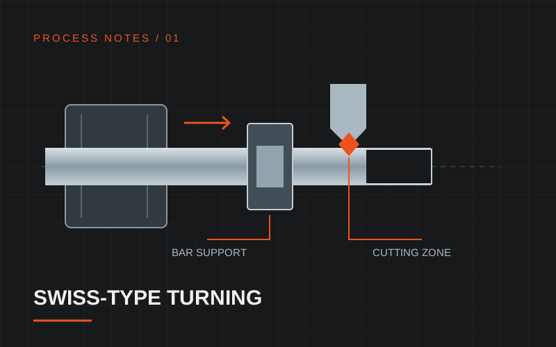
A long pin and a short bushing can have the same outside diameter but need different machining plans. For slender components, controlling how the workpiece is supported can be as important as selecting the cutting tool. This is where Swiss-type turning becomes relevant.
What makes Swiss-type turning different?
In a typical guide-bushing configuration, the sliding headstock feeds rotating bar stock through a support positioned close to the cutting zone. Keeping that unsupported distance short helps control bending during machining. Some Swiss-type machines can also operate without a guide bushing for suitable shorter parts; the configuration depends on the component and machine.
The term “Swiss screw machining” describes this family of processes. It does not mean that every component must be a screw: pins, shafts, sleeves and other turned features can also be candidates. Machine-builder documentation illustrates the available guide-bushing and non-guide-bushing configurations.
Select the process around the part
Start with the relationship between length, diameter and the features that must remain aligned. A slender shaft raises different workholding questions from a compact flange. Cross-holes, flats, threads and rear-face features also affect the required tooling and operation sequence.
Swiss-type turning is one possible route. Conventional CNC turning, supported turning or a combination of turning and secondary operations may be appropriate for other geometries. Compare the complete route, including setup, material preparation and inspection, against the quantity and required delivery.
Put functional requirements on the drawing
Give the machining team a clear view of how the component works:
- Mark the diameters and shoulders that locate mating parts.
- Define geometric controls where alignment or form affects assembly.
- Identify sealing, sliding and cosmetic surfaces separately.
- Specify thread size, pitch, usable depth and any checking requirement.
- Describe acceptable edge breaks and areas that must be free of burrs.
A single tight tolerance applied to every feature obscures priorities. Specific requirements on functional features make the production and inspection plan easier to review.
Review quantity and inspection together
For a prototype, setup effort and design flexibility may dominate the quotation. For a repeat batch, stable material supply, tool condition and inspection frequency become central. Ask which characteristics will be checked on the first article and which will be monitored during production.
A useful RFQ package includes a STEP or STP model, a dimensioned PDF drawing, material grade, quantity and revision. Add the mating-part information when the fit cannot be understood from the component drawing alone.
Send these details to the MechVibe factory team. We will review the geometry, critical features and inspection needs before confirming the proposed production route.