
Design for manufacturing
Sheet Metal Fabrication: Design Checks Before Quotation
by MechVibe Team · 3 min read
Review thickness, bends, hole placement, hardware and finish requirements for brackets, covers and enclosures.
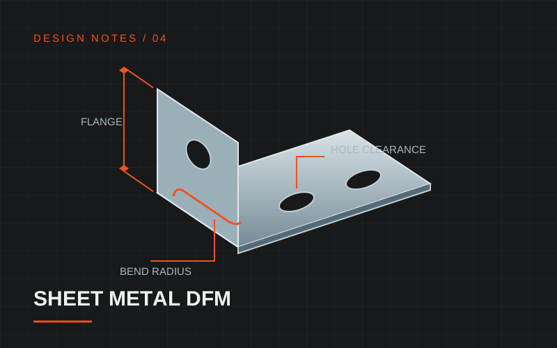
A bracket that looks simple in CAD can require several manufacturing decisions. Sheet thickness, bend sequence, hardware access and finish all affect whether the part can be formed and assembled as intended. Review these details before requesting a quotation.
Start with the material and thickness
Specify a material grade and nominal sheet thickness. Keep the base thickness consistent across the formed part, and distinguish separate welded pieces in the drawing. Include material condition when it affects forming or service performance.
For an enclosure, identify the surfaces and interfaces that define assembly. The outside envelope, mounting pattern and door or cover fit may need different controls from non-functional edges.
Check bends as physical operations
A bend has an inside radius; a sharp CAD corner does not represent the formed geometry. Radius and flange choices must work with the material and available tooling. Consistent radii can simplify production, while short flanges and closely spaced bends need particular attention. Protolabs' sheet metal design guidelines illustrate these relationships.
Consider the sequence as well. An early bend must not prevent the tooling from reaching a later bend. Where formed sides meet, suitable relief can help avoid unwanted distortion. Exact limits should be confirmed for the proposed process rather than copied from a different supplier's tooling rules.
Keep holes and hardware clear of bends
Holes or slots close to a bend can distort during forming. Check their distance from the bend and decide whether they can be moved or require another operation. Protolabs' bend-radius guide discusses this hole-placement issue.
For installed nuts, studs or other hardware, specify the part type, installation side and location. Make sure the formed shape leaves access for installation and for the fastener used during final assembly.
Plan joining and finishing together
If welding is required, identify the joints and any cosmetic or sealing expectations. Discuss how distortion will be managed at functional interfaces.
State whether the part is supplied bare, plated, anodized or powder coated. Mark areas that need masking, including threads and contact surfaces. Coating thickness can affect fits, so finished dimensions should be identified where necessary.
Send the files needed for review
A clear package includes:
- A formed STEP or STP model and dimensioned PDF drawing.
- Material grade, thickness, quantity and revision.
- Critical assembled dimensions and bend requirements.
- Hardware, joining and surface-finish details.
- A DXF flat pattern if available, with its status clearly identified.
The flat pattern and formed model should describe the same revision. MechVibe can review the requirements with your quotation and clarify manufacturing details before the order is approved.